Building a Binary Counter
08 Feb 2021
A binary counter is an electronic component that records the number of times it has received a pulse. It is called binary because it stores the number in its binary representation. Counters are absolutely ubiquitous in electronics and can be used to make circuits ranging from memory chips to FM radio decoders.
Since counters are so useful, I thought it would be fun to implement one using only basic logic gates like NAND and OR. As a practical application, I hooked up a 1-bit counter to a clock and a pair of LEDs to create a random bit generator:
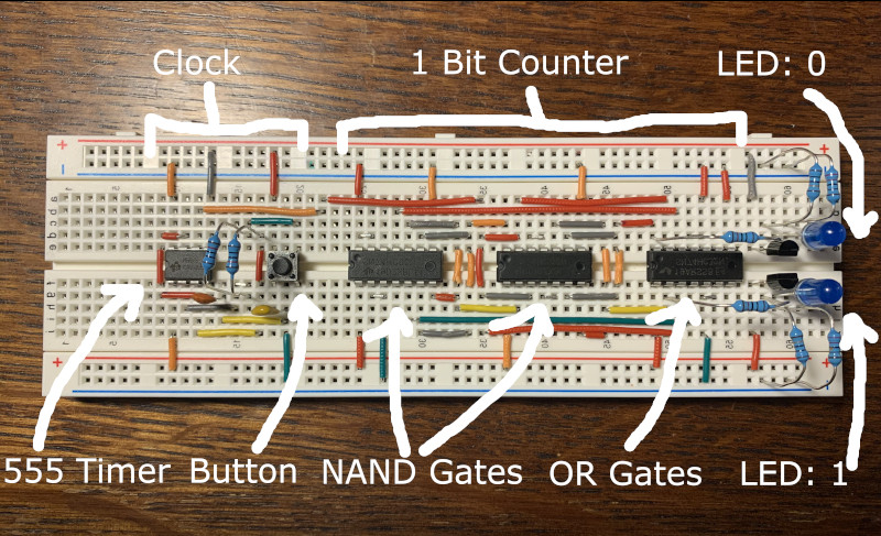
The output of the counter is connected to two LEDs. One of them lights up when the counter is in the 0 state and the other lights up in the 1 state. When the button is pressed down, the clock starts sending out around 100 pulses per second causing the counter to oscillate between 0 and 1. When the button is released the timer stops and the the counter remains in its most recent state as indicated by the corresponding LED. The state is maintained until the next time the button is pressed.
Since the oscillations are very fast relative to human reflexes, the LED that remains lit after each button release appears to be chosen randomly with each LED appearing with equal probability. In other words, one can think of this circuit as simulating a coin flip where one of the LEDs represents heads and the other tails. At the end of the post I will provide some evidence that two outcomes are indeed equally likely.
The primary goal of this post is to explain how to make a 1 bit counter out of basic logic gates. After that we’ll get into the details of the complete random bit generator circuit shown above. We’ll conclude by showing how multiple 1 bit counters can easily be chained together to produce larger counters such as the useful 8 bit counter.
The 1 Bit Counter
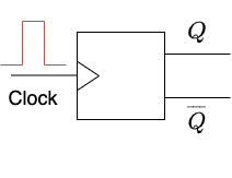
Here is a high level schematic of the one bit binary counter we want to build:
We now turn to the design requirements.
The counter has a single input which is labelled “Clock” and two outputs labelled $Q$ and $\overline{Q}$. The input and output wires can either have a “high” voltage or a “low” voltage. In our case, we will be using a 5 volt power supply so a “high” wire will be close to 5 volts and a “low” wire will be close to 0 volts.
The overline on the bottom output represents the fact that its state is always opposite to $Q$. I.e, if $Q$ is high then $\overline{Q}$ is low and vice versa. It may seem redundant to include both $Q$ and $\overline{Q}$ but later we will see why it is useful. We summarize the state of the counter by writing $Q=1$ if $Q$ is high and $Q=0$ if $Q$ is low.
As long as the clock input is low the output state should remain fixed. But each time the the clock receives a pulse (explained below) the values of the outputs should flip.
In more detail, a “pulse” means that the clock input rises from low to high, and then quickly falls back to low. Since the output should only change one time per pulse, we would like the outputs to flip whenever the clock input rises from low to high. This special behavior is indicated by the triangle next to the clock input.
You may be wondering why we need this fancy pulse behavior. Why can’t we simply demand that the outputs flip whenever the input is high? The issue with that design is that every pulse has some non-zero duration. So even a short pulse would cause the outputs to start rapidly flipping back and forth from the moment the clock input went high until the end of the pulse when it went low again. This would make the final state undefined!
In contrast, the input voltage rises from low to high exactly once per pulse so our design guarantees that the outputs will flip exactly once whenever the input receives a pulse.
Now that we’ve specified the counter’s behavior we turn to the implementation.
There are two main implementation challenges. First, how does the counter maintain its state between pulses? Second of all, how is it possible to detect the low to high transition exactly once per pulse?
In the next section we focus on the first issue by considering a simpler type of component that has two separate “on” and “off” inputs rather than the complex clock input. We will then solve the pulse problem by chaining two of these simpler components to each other!
The SR Flip-flop
In this section we’ll build a component called the Set Reset Flip-flop or SR Flip-flop for short.
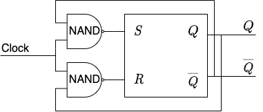
Here is a diagram of the SR flip-flop:

This flip-flop has two inputs: $S$ (“set”) and $R$ (“reset”) and two outputs: $Q$ and $\overline{Q}$. As before, $\overline{Q}$ always has the opposite value of $Q$. So if $Q$ is high then $\overline{Q}$ is low and vice versa.
In its default state, both inputs $S$ and $R$ are high and the output $Q$ is low. If $S$ is pulled low (i.e $S=0$) this sets the gate and causes the output $Q$ to be high (and therefore $\overline{Q}$ to be low). The output will stay in this state even when $S$ goes high again. On the other hand, pulling $R$ low resets the gate which means that $Q$ will go low. As before, $Q$ will remain low even when $R$ goes back to being high.
In summary, we can flip between the two possible output states by lowering either $S$ or $R$. Furthermore, the SR flip-flop maintains its state until the next set or reset operation.
It turns out that it is possible to build an SR latch out of just two NAND gates via an ingenious mechanism called the NAND latch as shown in the following diagram:
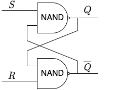
We are using the convention that an “X” intersection of wires means that the wires do not touch but rather cross over each other.
How does this circuit work? Lets see what happens if we start in the defaults state ($S=R=\overline{Q}=1$, $Q=0$) and perform a set operation:
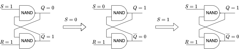
In the initial state the input to the top NAND is $(1, 1)$ and so its output is $Q=0$. The input to the bottom NAND is $(0, 1)$ so its output is $\overline{Q}=1$. Since everything is consistent, the gates will stay in this configuration until we change one of the the inputs.
Now lets perform a “set” operation by pulling down $S$ to a low state to get $S=0$. Since one of the inputs to the top NAND is $0$, its output will be $Q=1$ regardless of the other input. This means that the input to the bottom NAND is $(1, 1)$ causing its output to be $\overline{Q}=0$.
Finally, lets see what happens if we release $S$ and let it go back to the default high state $S=1$. The input to the top NAND is now $(1, 0)$ which means that its output is still $Q=1$. Therefore the output to the bottom NAND is still $(1, 1)$ causing its output to stay at $\overline{Q}=0$.
In summary, we can see that one cycle of $S=0 \Rightarrow S=1$ sets the output to $Q=1,\,\overline{Q}=0$. A similar analysis shows that a cycle of $R=0 \Rightarrow R=1$ resets the output to $Q=0,\,\overline{Q}=1$.
A 1-Bit Counter Implementation
We now return to the problem of building a one bit counter. The SR flip-flop from the last section gets us pretty close: It has the outputs $Q$ and $\overline{Q}$ and allows us to toggle between them by pulling down $S$ or $R$. To turn this into a counter we need to replace the set/reset inputs with a single clock input.
The general logic should be:
- If the clock is low then then the SR inputs should be in their default state of $S=R=1$. This will result in $Q$ maintaining its current state.
- If the clock is high and $Q=1$, reset the SR flip-flop by setting $R=0$. This will result in $Q=0$.
- If the clock is high and $Q=0$, set the SR flip-flop by setting $S=0$. This will result in $Q=1$.
We can implement this logic by wiring up an SR flip-flop with two NAND gates like so:
As before, wires that meet in an X intersection do not touch each other. We’ve connected the $Q$ output to the bottom NAND and the $\overline{Q}$ output to the top NAND.
Let’s verify that this circuit follows the logic outlined above. Indeed, if $\mathrm{Clock}=0$ then both of the NANDs will have a $0$ input and so their outputs will always both be $1$. This means that the two inputs to the SR flip-flop will be in their default $1$ state as desired.
What happens when the clock goes high ($\mathrm{Clock}=1$)? Suppose that $Q=1,\,\overline{Q}=0$. Then the inputs to the top NAND will be $(\overline{Q}=0, \mathrm{Clock}=1)$ and so its output will be $1$. On the other hand, the inputs to the bottom NAND will be $(\mathrm{Clock}=1, Q=1)$ so its output will be $0$. Together this means that the input to the SR flip-flop will be $S=1$, $R=0$ which by definition will reset the flip-flop to $Q=0,\,\overline{Q}=1$.
If the clock goes high again it is not hard to see that the SR inputs will now be $(S=0,\,R=1)$ causing it to set the output back to $Q=0,\,\overline{Q}=1$.
The only problem with this setup is that the outputs will keep flipping as long as the clock is high! Since each clock pulse has some non-zero duration, this version of the counter will flip many times per pulse rather than just once.
The solution is to use two SR flip-flops. One will record the current output and the other will record the output for the next pulse. The trick is that the “current” flip-flop is activated when the clock goes high as above, but the “next” flip-flop will be activated when the clock goes low. The effect is that the counter is only updated after a complete cycle $\mathrm{Clock}=0 \Rightarrow \mathrm{Clock}=1$, preventing the oscillations in our first version.
Here is an implementation of this idea:
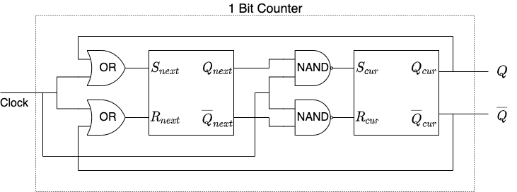
When the clock is low it is easy to see that $S_{cur}=R_{cur}=1$ meaning that the “current” flip-flop will not be updated. In contrast, when the clock is high $S_{next}=R_{next}=1$ and so the “next” clock will not be updated. It is not hard to verify that with this version the outputs $Q,\,\overline{Q}$ flip exactly once when the clock receives a pulse.
A Random Bit Generator
In this section we will use a 1 bit counter to build the random bit generator we described in the introduction. In addition to being a fun gadget, this will be an opportunity to place the counter in a complete working circuit.
Here is the circuit diagram for the random bit generator:

At the top left we have a 555 timer wired in astable mode. When the button is pressed it will send pulses to the 3 pin with a frequency of about 100hz.
Our 1 bit counter is layed out along the bottom. We’ve used two 74HC00 chips for the NAND gates and a 74HC32 chip for the OR gates. For convenience, I’ve drawn the connections of the logical gates that are inside these chips but these are for visualization only.
Finally on the top right there are two LEDs, each one connected to a different output of the counter. These connections are done via transistors so that the LEDs do not steal too much voltage from the logic gates.
When the button is pressed down, the timer will start sending pulses out of the 3 pin of the 555 chip. Each pulse will flip the output of the counter which in turn causes exactly one of the LEDs to light up. When the button is released the pulses stop and which ever LED happens to be on will stay on until the next time the button is pressed.
To test whether the LEDs have an equal chance of being on after the button release I pressed the button 100 times and recorded which light stayed on. Here is the result with one of the lights represented by a 0 and the other by a 1:
00110000000111001110011101001010000110101101111101
10011000110011101100010100000101010001000110111111
There are 51 0s and 49 1s in the sequence so we can conclude with 95% confidence that the probability of getting a 1 is within $\frac{1}{\sqrt{100}} = 0.1$ of the sample mean $49 / 100 = 0.49$. In other words, the probability of getting a 1 is between $0.39$ and $0.59$. We could reduce the error bounds by pressing the button more times but this seems good enough for a demonstration.
Adding More Bits
It is easy build an N-bit binary counter out of N 1-bit counters. The idea is that when the output of the lowest order 1-bit counter switches to 0 this should flip the counter of the next lowest bit so that we “carry the 1”. Here is an example of an 4-bit binary counter:

Each square represents a 1-bit counter. The lowest order bit $b_0$ is on the left and the highest order bit $b_3$ is on the right.
Initially all the bits are set to 0 and so the full output of the counter is 0000. When the clock rises from low to high the leftmost bit counter will be triggered causing $Q_0$, and by extension $b_0$, to be set to 1. The full output will now be: 1000.
The next time the clock rises will cause $Q_0$ and $b_0$ to flip back to 0. Furthermore, $\overline{Q}_0$ will rise from low to high triggering the next 1-bit counter and causing $b_1$ to be set to 1. So the final output after the second pulse will be 0100.
Continuing in this fashion it becomes clear that after $N$ pulses the output will contain the binary representation of $N$ modulo $2^4=16$ where the binary number is read from left to right.
Incidentally, note that this is one application where it is handy to have the $\overline{Q}$ outputs around in addition to the $Q$ outputs.
Comments
The comments are powered by the utterences Github app. If you do not want the app to post on your behalf, you can comment directly on this Github issue.